


Description
Intro:
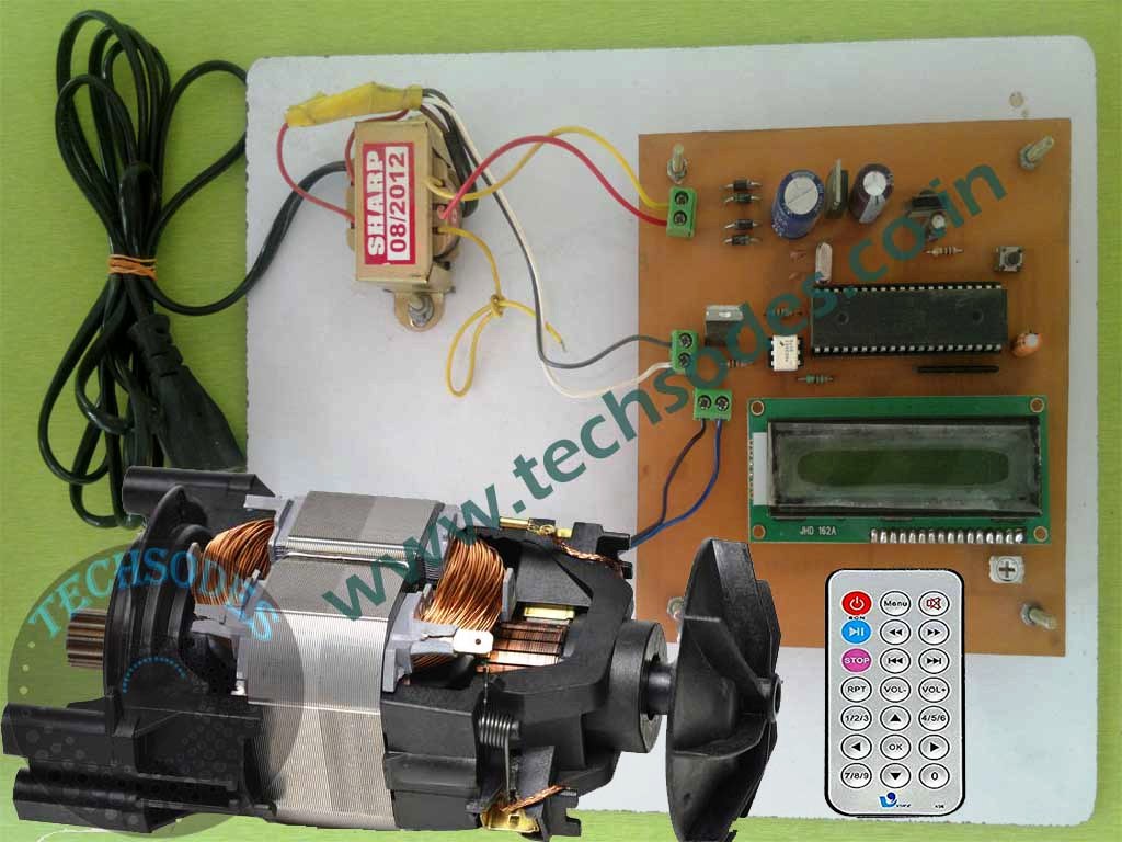
The **Induction Motor Speed Control Using IR Remote with ZVS** is a project designed to control the speed of a single-phase induction motor using an 8051 microcontroller. This project employs a combination of zero-voltage switching (ZVS), TRIAC, opto-isolators, and an IR remote for seamless speed control. The system can handle motors up to 1HP (220V) and is an efficient way to manage motor speed using non-mechanical methods like infrared communication.
1. Project Overview
This system utilizes an 8051 microcontroller to receive input from an IR remote control and adjust the speed of an induction motor accordingly. The motor’s speed is displayed on a 16×2 LCD screen, providing real-time feedback to the user. The microcontroller controls the motor’s speed through a TRIAC BT136, driven by the opto-isolator MOC3021, allowing phase-angle control of the AC motor.
The power supply for the entire circuit is provided by a 12-0-12/500mA transformer. The AC voltage from the transformer is rectified using a 4007 diode bridge to produce DC, and a 7805 voltage regulator is used to provide a stable 5V supply for the microcontroller and other components.
2. Components Used
8051 Microcontroller:
The 8051 microcontroller acts as the brain of the system. It receives signals from the IR remote and processes the input to control the motor’s speed by adjusting the phase angle of the AC voltage delivered to the motor. This microcontroller handles all necessary computations and control logic.
16×2 LCD:
A 16×2 LCD is used to display the current speed of the motor. This user interface provides feedback on the motor’s operational state, allowing the user to monitor speed changes and ensure the motor is running at the desired speed.
IR Receiver TSOP-1738:
An IR receiver module is used to detect the signals from the IR remote. The microcontroller processes these signals to change the motor speed, making it possible to increase or decrease the motor’s speed with the remote’s buttons. This eliminates the need for physical contact and manual intervention, enabling wireless control of the system.
Opto-Isolator (MOC3021):
The MOC3021 is an opto-isolator used to drive the TRIAC, isolating the control side (low voltage) from the power side (high voltage) of the circuit. When the microcontroller triggers the opto-isolator, it allows safe switching of the AC power that drives the motor without introducing electrical noise into the microcontroller.
TRIAC (BT136):
The BT136 TRIAC is used for controlling the AC motor’s speed by modulating the power delivered to the motor. The TRIAC works in conjunction with the MOC3021 to manage the phase angle of the AC voltage, thus allowing for variable speed control. The TRIAC is capable of handling motors with up to 1HP (220V) power ratings, making it suitable for a variety of applications.
Power Supply:
The entire circuit is powered by a 12-0-12/500mA transformer. The AC voltage from the transformer is first rectified using a 4007 diode bridge to convert it into DC. Then, a 7805 voltage regulator is used to step down the voltage to a stable 5V, which powers the microcontroller, IR receiver, and other low-power components. This power supply ensures that the control system remains stable and reliable.
Zero Voltage Switching (ZVS):
ZVS is used to switch the TRIAC at the point where the AC waveform crosses zero volts, reducing the electromagnetic interference and stress on the components. By using ZVS, the project improves efficiency and extends the lifespan of the motor and switching components. This method ensures that the TRIAC switches on only at the zero voltage point, reducing wear on the motor and improving overall control.
3. Operation of the System
The induction motor speed control system operates by adjusting the amount of power supplied to the motor using phase-angle control. The TRIAC modulates the phase angle of the AC supply, which in turn changes the effective voltage supplied to the motor. The microcontroller uses inputs from the IR remote to determine how much to adjust the phase angle.
IR Remote Control:
The IR remote serves as the user interface for controlling the motor’s speed. When a button on the remote is pressed, the IR receiver detects the signal and sends it to the microcontroller. The microcontroller interprets the signal, either increasing or decreasing the motor speed based on the input.
Speed Control Mechanism:
The microcontroller adjusts the phase angle at which the TRIAC switches on, thereby controlling the motor’s speed. For lower speeds, the TRIAC is triggered later in the AC cycle, reducing the effective voltage delivered to the motor. For higher speeds, the TRIAC is triggered earlier in the cycle, increasing the voltage. The ZVS ensures that switching occurs at the zero-crossing point of the AC waveform, which reduces the amount of electrical noise and ensures smoother operation.
LCD Display:
The 16×2 LCD continuously displays the current speed of the motor in terms of a numerical value. This real-time feedback allows the user to monitor the motor’s performance and make precise adjustments using the IR remote. The speed is displayed as a percentage or RPM, depending on how the system is calibrated.
4. Power Supply Circuit
The power supply circuit uses a 12-0-12/500mA step-down transformer to reduce the mains voltage (220V) to a manageable 12V AC. This AC voltage is rectified using four 4007 diodes arranged in a bridge configuration, converting it into DC. After rectification, the DC voltage is regulated using a 7805 voltage regulator, which provides a stable 5V output to power the microcontroller, IR receiver, LCD, and other low-power components.
5. Applications
This project is suitable for various applications where induction motors are used and precise speed control is necessary. These include:
– **Fans**: The system can be adapted to control fan speeds in industrial or domestic environments.
– **Pumps**: Water or chemical pumps with induction motors can be efficiently controlled using this system.
– **HVAC Systems**: Heating, ventilation, and air conditioning systems can benefit from precise motor speed control, improving efficiency and reducing power consumption.
6. Conclusion
The Induction Motor Speed Control Using IR Remote with ZVS is a highly efficient system designed for easy, wireless control of induction motors. Using an 8051 microcontroller, ZVS, TRIAC BT136, and an IR remote, this project provides a seamless and user-friendly solution for varying motor speeds. The inclusion of ZVS ensures that switching occurs at optimal points, reducing electrical noise and prolonging the lifespan of the motor and other components. This system offers a practical and cost-effective solution for controlling induction motors in a wide range of applications.

Reviews
There are no reviews yet.