Description
Intro:
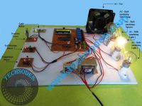
The Metro Train Control System is a comprehensive project designed to manage the movement of a toy train on a track using an 8051 microcontroller (W78E052DDG), multiple sensors, motor drivers, and RF communication. The system involves a ground station that controls the train’s movement, manages road barriers, and simulates realistic metro train functionalities, such as automatic stop when detecting obstacles and fire alarms for safety and train track brack safety .
1. System Overview:
The system uses an 8051 W78E052DDG microcontroller as the central controller at the ground station, which receives input from various sensors and manages outputs like motor drivers, barriers, and signals. It communicates wirelessly with a toy train, which has an embedded system controlled by an 89C2051 microcontroller.
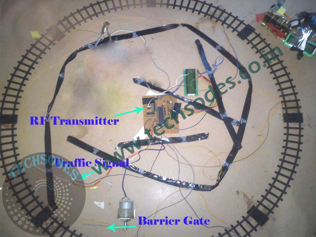
The system also includes a track break wire loop, which ensures that if there is a break in the train track, the toy train is automatically stopped. This safety feature enhances the realism of the project by simulating real-world train system failures where train movement is halted if there are issues with the tracks.
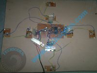
At the ground station, five reed switches are installed along the train track to detect the train’s position at three stations and manage the road crossing barrier. The system uses traffic light signals (red, green, yellow LEDs) to indicate the train’s status, such as whether the road crossing is safe or the train is approaching.
2. Components Used
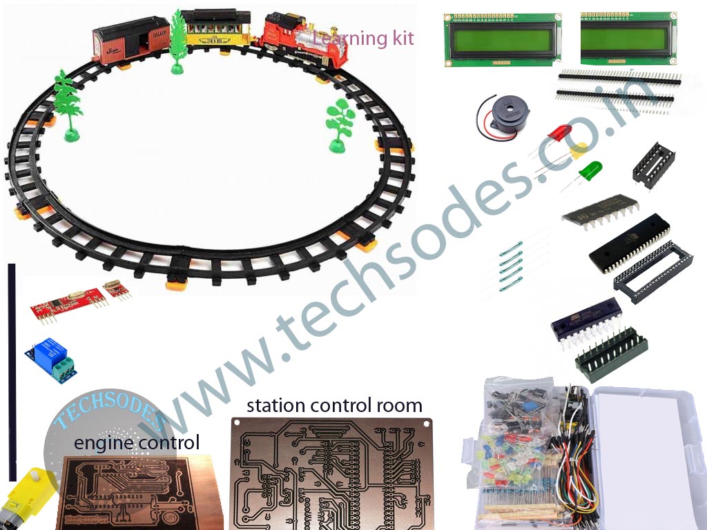
Microcontroller (8051 W78E052DDG)
The main controller at the ground station, this microcontroller receives signals from reed switches (magnet sensors) and controls outputs like the traffic lights and the DC motor for the road barrier.
Reed Switches
There are five reed switches placed along the track to detect the train’s location:
– Switch 1: Detects when the train reaches Station 1.
– Switch 2: Detects when the train reaches Station 2.
– Switch 3: Detects when the train reaches Station 3.
– Switch 4: Closes the road crossing barrier when the train approaches.
– Switch 5: Opens the barrier after the train passes.
Traffic Light System
Three LEDs (red, green, yellow) are used to simulate traffic signals at the road crossing. The green LED allows vehicles to pass, the yellow LED signals caution, and the red LED indicates the train is approaching, and the barrier closes.
Motor Driver (L293D)
This motor driver controls the DC motor that operates the barrier at the road crossing. When the train is detected by the reed switches near the crossing, the L293D motor driver activates the motor to either close or open the barrier.
RF Communication
The HT12E encoder and HT12D decoder are used to establish RF communication between the ground station and the toy train. The RF transmitter at the station sends control signals to the RF receiver on the train, which are then decoded and used to manage the train’s engine through the 89C2051 microcontroller.
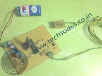
Train Engine (Toy Train) with 89C2051 Microcontroller
The toy train is equipped with an 89C2051 microcontroller that controls its movement. It receives control signals from the ground station via the RF receiver and the HT12D decoder. Additional functionalities include:
– **Buzzer**: The train’s buzzer sounds twice before the train starts moving to simulate real-world metro train announcements.
– **Fire Sensor**: This sensor detects fire inside the train, activating the buzzer for safety alerts.
– **Relay**: A relay is used to control the on/off state of the train’s motor, allowing the system to stop or start the engine based on signals received.
– **IR Object Sensor**: Positioned in front of the train, this sensor detects any obstacles in the train’s path, automatically stopping the train to prevent collisions.
3. System Operation
1. Train Movement Control
As the train moves along the track, reed switches detect its position and send signals to the 8051 microcontroller. Based on the train’s location, the system triggers different actions:
– At Station 1, 2, and 3, the system knows the train’s exact location.
– When the train is approaching a road crossing (detected by the 4th reed switch), the system closes the barrier by activating the DC motor through the L293D motor driver.
– After the train crosses, the 5th reed switch signals the system to open the barrier, allowing vehicles to pass.
2. Traffic Light Signal
The LEDs at the road crossing help simulate real-world traffic control:
– When the train is far from the crossing, the green LED is on, allowing vehicles to pass.
– As the train approaches, the yellow LED flashes, signaling caution.
– When the train is near the crossing, the red LED turns on, and the barrier closes.
3. Wireless Control of Toy Train
The ground station controls the toy train wirelessly using RF communication. The HT12E at the ground station encodes control data and transmits it to the HT12D on the train. The 89C2051 microcontroller onboard the train then decodes these signals and controls the train’s motor and other components accordingly.
Realistic Train Features
To enhance realism, the system includes features such as a buzzer that sounds twice before the train starts moving, similar to announcements in real-world metro trains. Additionally, the train has a fire sensor for safety, which triggers a buzzer in case of a fire. The IR object sensor ensures that if an obstacle is detected ahead, the train automatically halts to avoid collisions.
4. Safety and Realism
Safety is a key aspect of this project. The fire sensor on the train ensures that if a fire breaks out, an immediate alert is raised through the buzzer. Additionally, the IR sensor on the front of the train prevents accidents by stopping the train if another object is detected on the track.
The buzzer that sounds before the train starts and the automated road crossing barrier system contribute to the realistic functioning of the system, making it a practical prototype for educational and demonstration purposes.





Reviews
There are no reviews yet.