Description
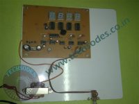
Speed Control Of DC Motor Using Pulse-Width Modulation with mosfet
PWM (Pulse Width Modulation) is a widely used technique for controlling the speed of DC motors by varying the duty cycle of a digital signal. In this method, the average voltage across the motor is controlled by adjusting the pulse width of the signal, allowing smooth and efficient speed variation.
A PWM signal alternates between high and low states, and the ratio of the “on” time to the total period is called the duty cycle. If the duty cycle is 0%, the motor receives no voltage and remains off, while a 100% duty cycle corresponds to the motor receiving full voltage and running at maximum speed. By controlling the duty cycle, the motor’s average voltage and speed can be adjusted.
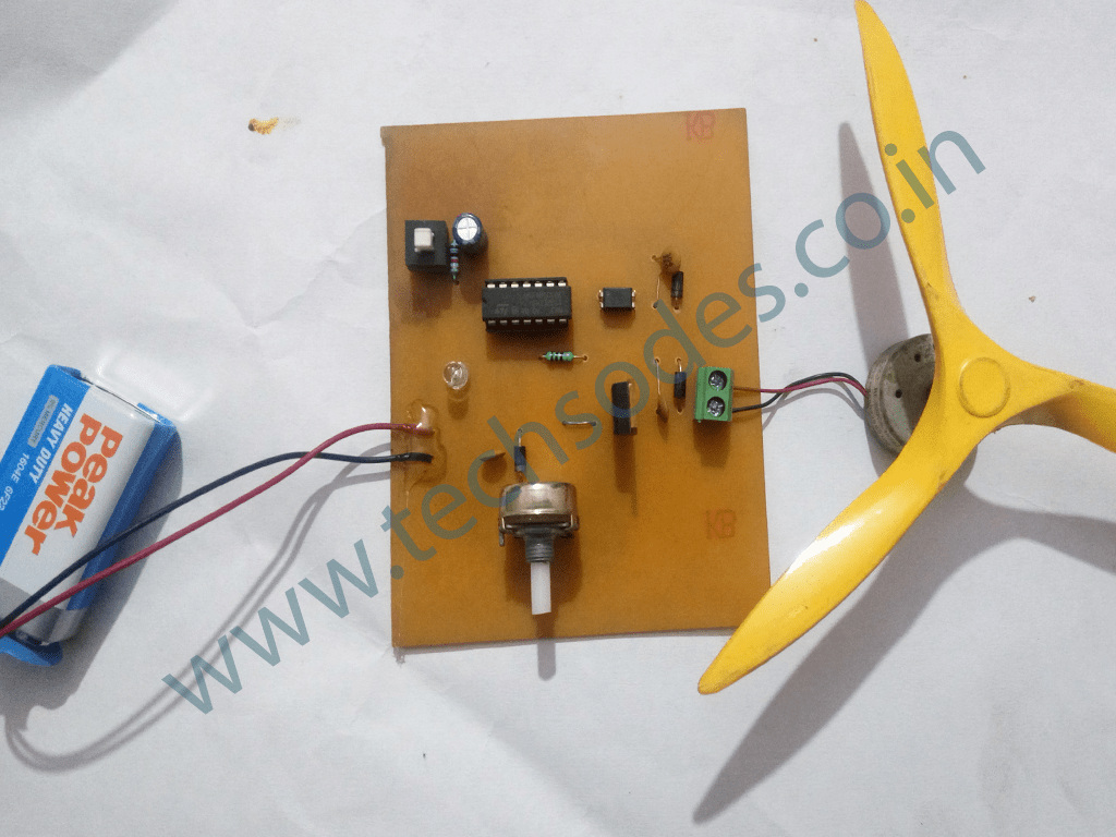
In your case, you implemented a simple PWM circuit for controlling a DC motor commonly found in toys or tape recorders. The circuit generates a PWM signal using an astable multivibrator based on a Schmitt trigger inverter. This Schmitt trigger is used to ensure that the output is a clean digital signal. A potentiometer (VR1) is used to vary the duty cycle of the PWM signal, allowing you to control the speed of the motor smoothly from zero to full speed.
Working of the Circuit
The circuit’s core consists of a Schmitt trigger inverter configured as an astable multivibrator, generating a square wave at a constant frequency but with a variable duty cycle. The duty cycle is controlled by the potentiometer (VR1), which adjusts the pulse width. By moving the wiper of the potentiometer, the proportion of the positive and negative periods of the square wave changes, thus altering the duty cycle. This means that the motor’s speed can be finely tuned by adjusting the potentiometer, with the motor receiving more voltage as the duty cycle increases.
The generated square wave is then passed through another Schmitt trigger gate (N2), which acts as a buffer to drive the transistor or MOSFET that controls the motor’s power. This buffer ensures that the control signal is strong enough to switch the transistor or MOSFET on and off effectively.
The transistor, usually a bipolar junction transistor (BJT), is used to switch the motor on and off based on the PWM signal. When the transistor is turned on, the motor is connected to the power supply, and when it is turned off, the motor is disconnected. The speed of the motor is directly proportional to the average voltage it receives, which is determined by the duty cycle of the PWM signal.
By varying the duty cycle, the motor’s speed can be smoothly controlled from fully off (0% duty cycle) to fully on (100% duty cycle). This method of speed control is highly efficient because the transistor or MOSFET is either fully on or fully off, minimizing the power lost as heat.
Key Components and Their Roles
1. Schmitt Trigger (N1 and N2): The Schmitt trigger is used to generate a clean square wave and buffer the control signal.
2. Potentiometer (VR1): This component is used to adjust the duty cycle, and thus control the motor speed.
3. Capacitors (C1, C2): These are used to store and release charge in the timing circuit, ensuring smooth voltage transitions and stable operation.
4. Transistor or MOSFET: This acts as the switch that connects and disconnects the motor from the power supply, based on the PWM signal.
5. Diodes: These provide different timing resistor values during the charging and discharging cycles of the timing capacitor, ensuring the PWM frequency remains constant.
Practical Applications
The PWM-based DC motor speed control circuit you have implemented has several practical applications:
1. Toys and Gadgets: Small DC motors are often found in toys, tape recorders, and other gadgets, where precise speed control is needed.
2. Home Automation: The circuit can be adapted to control small motors in home automation systems, such as fan speed control or motorized curtains.
3. DIY Projects: Hobbyists and DIY enthusiasts can use this circuit to control DC motors in a variety of projects, from robots to automatic machines.
Conclusion
The use of PWM for controlling DC motors is a simple yet effective method. By varying the duty cycle of the PWM signal, you can control the motor’s speed in a smooth and efficient manner. The circuit you have implemented, with a Schmitt trigger inverter generating the PWM signal and a potentiometer to adjust the duty cycle, provides a flexible and reliable way to control a DC motor’s speed.
This method ensures minimal power loss and allows for precise control, making it ideal for a wide range of applications, from toys and gadgets to DIY projects and small automation systems.






Reviews
There are no reviews yet.